Introducing AXCIOMA
Event Sender
In this third introduction article we creating an application that is going to publish DDS shapes with a configurable interval. This application can be deployed separately from our previous event receiver.
Definition
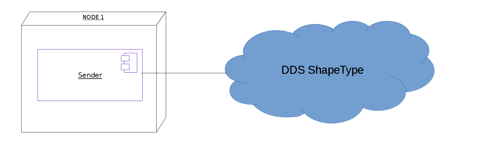
As in the previous article we are going to use the well known DDS Shapes interoperability demo. We want to create a component that sends DDS Shapes on a configurable interval. In AXCIOMA terminology this means we are going to write the ShapeType. The component model for this example is shown in Figure 1.
We are using the same IDL type definition as in our previous event receiver example.
typedef string<128> color_type;

@nested(FALSE)
struct ShapeType {
  color_type color; //@key
  long x;
  long y;
  long shapesize;
};
These IDL definitions are placed in the file shapes.idl which we store in a data subdirectory of our project
folder according to "AXCIOMA Best Practices".
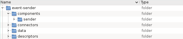
Figure 2 shows the complete directory tree for this example project.
Based on the defined datatype we can now go about creating the other parts of our implementation like the actual code for the datatype, the connector, and the component.
The first recipe to create is the project recipe placed in a file called aprc. It’s primary function is to mark the
root of the project directory tree and to specify a number of project global settings. For this example project
we create the following project recipe.
# common IDL include folder(s)
prj.idl_includes %w{ data }
This specified the data subdirectory as a common include directory for IDL compilation tasks.
Next thing we do is create a connector recipe for the implementation of our chosen event interaction
pattern for the ShapeType datatype. The implementation of choice is a DDS4CCM connector so we create the following
connector recipe in the file connectors/event_dds4ccm_conn.aprc.
connector 'shapes' do |conn|
  conn.idl %w{ shapes.idl }
  conn.port_type :dds4ccm do |tp|
    tp.topic 'ShapeType'
  end
end
This specifies a connector recipe named shapes which is to use (include) the IDL file shapes.idl (to be found by
searching any defined IDL include paths like the one specified in the project recipe) to define a DDS4CCM connector
for the topic ShapeType interface. The topic type
definition must be defined in the scope of the included IDL file(s).
In AXCIOMA this is all that is needed to create a completely implemented connector as you will see later on!
Going on we move to creating a component recipe for the component sending ShapeType samples. This recipe will be
placed in the file components/sender/sender.aprc.
component 'shapes_sender' do |comp|
  comp.idl %w{ shapes.idl}
  comp.define 'sender' do |intf|
    intf.port 'shape' do |p|
      p.writes 'ShapeType'
    end
    intf.port 'timer' do |p|
      p.timed_trigger
    end
    intf.attribute 'rate',type: 'short'
  end
end
This specifies a component recipe named shapes_sender for a component using the IDL file shapes.idl.
In this example we define a component sender having two port definitions and one attribute.
First a single shape port definition with extended port type ShapeTypeInterface::DDS_Write.
Second a timer port which is going to use a timed trigger which is provided by the
AXCIOMA TT4CCM connector. Using the AXCIOMA timed trigger support you do not have to use
lower level threading or timer APIs and it also provides an easy upgrade path to use the AXCIOMA Execution Framework
(ExF).
Lastly we define an attribute rate of type short.
The generated IDL will look like this.
#include <Components.idl>
#include <ccm_timed_trigger.idl>
#include "shapesSE.idl"
component sender
{
provides CCM_DDS::ConnectorStatusListener connector_status_ShapeType;
port ShapeTypeInterface::DDS_Write shape;
uses CCM_TT::TT_Scheduler timer;
attribute short rate;
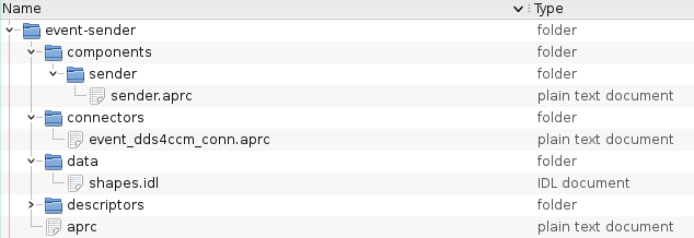
};After creation of the type IDL file and the BRIX11 APC recipes our project tree looks like the picture shown in Figure 3.
Notice that up to this moment we only defined ShapeType datatype in IDL and described the basic properties of our component and connector using fairly simple recipe directives.
In AXCIOMA that is all it takes to be able to start a new project because the BRIX11 APC commands are able to fill in the required blanks and generate all other information/files required for your project after which you will have only relatively little coding left to do to complete your components as you will see in the next section.
Preparation
Now that we have defined the datatype and how to organize our component and connector we can use BRIX11 APC to set up the details.
First we will have BRIX11 APC create a full set of project (build) files for our chosen development
environment. In our case this means generating GNU makefiles to drive IDL and code compilation and linking but when
using an AXCIOMA package for Microsoft Visual C++ on Windows BRIX11 APC will (by default) generate solution files.
To execute this step we run the following command anywhere from the project directory tree (BRIX11 APC will always
automatically determine the project root by looking up the project recipe file aprc).
$ brix11 apc prepare
When execution of this command finishes our project tree will contain all necessary project build files as shown in Figure 4.
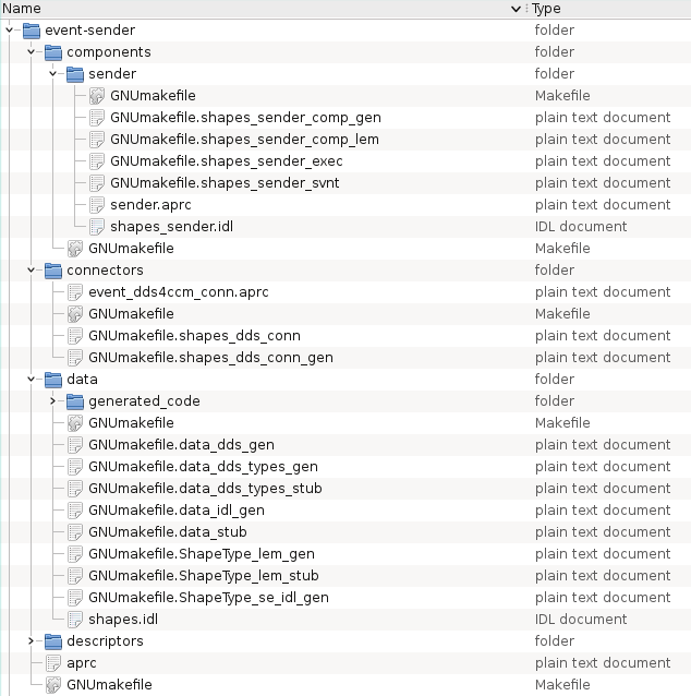
As you can see the brix11 apc prepare command not only generated the project files though. In the component directory we
now also find the IDL file defining the component as specified in the component recipe we created.
The generated project files take into account all the dependencies and build steps BRIX11 APC has been able to analyze from the IDL type definition files used as well as the directives of the collective recipes.
APC will generate also all needed dependencies and build steps for the necessary DDS based support. As user you don’t need to manually invoke the DDS vendor IDL compiler and compile all source files generated.
With the project files generated we are ready to start coding and building but instead of coding ourselves we will have the AXCIOMA tooling take care of a large part of that.
A large part of AXCIOMA application implementations is created through automatic code generation by the RIDL parser/generator included with AXCIOMA. The project files generated by BRIX11 APC have been set up to take full advantage of the possibilities of RIDL.
Executing the buildsteps defined by the project files will create (and build) a complete set of code files for the application including full datatype and connector implementations as well as skeleton implementations for the component. The executor code generated for the sender component is furthermore provided with regeneration markers. The buildsteps configured for this code will regenerate this code when needed (when IDL changes) protecting any user code between regeneration markers. The generated skeleton code for the component provides complete yet empty implementations designed to be able to validate the structural dependencies within the project by building and deploying.
Using BRIX11 APC we do not even need to worry about the actual build tools to use for the environment we are working in. Executing the following command will have BRIX11 APC take care of running the correct tools to compile IDL and code files and build the resulting binaries.
$ brix11 apc build
As with the brix11 apc prepare command this command too can be executed from anywhere within the project directory tree.
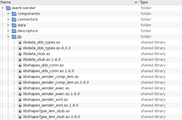
When execution of this command finishes our project tree will be filled with a large collection of code files and
build artifacts and (if everything went well) all runtime binaries (shared libraries) collected under the lib
subdirectory as shown in Figure 5.
Most of the generated code can be found in separate subdirectories which (by default) are called generated_code
(you will find these below the data, connectors and component directories).
The code in these directories is to be considered transient. The AXCIOMA build commands configured in the generated
project files will regenerate these files as needed based on IDL definitions and recipe directives disregarding any
changes made (additionally the standard cleanup commands of the build tools will delete these files and directories).
The exception to this rule concerns the component executor code. This is the part where the user (you) will have to
implement the required business logic. The files containing this code are generated (by default) in the directory
holding the component recipes (and IDL files) with names derived from the recipe id appended with _exec.{cpp,h}.
Figure 6 shows how this looks like for the sender component directory.
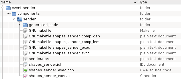
The executor code itself is provided with regeneration markers at appropriate locations in the code for the user to add there own definitions and implementations in a way that safeguards these changes for regeneration of the executor code.
Implementation
To make sure we can see this example actually doing something we will need to add some "business logic" to the component.
Because we want to react on a timer we have to implement a callback class that is derived from the
IDL::traits<CCM_TT::TT_Handler>::base_type trait. The on_trigger method is called at the moment
the timer expires and we will have that method write a sample to DDS and increment the x and y position of our
sample.
//@@{__RIDL_REGEN_MARKER__} - BEGIN : sender_Impl[user_namespace_impl]
class TT_Callback final
  : public IDL::traits<CCM_TT::TT_Handler>::base_type
{
public:
  TT_Callback (IDL::traits< CCM_sender_Context>::ref_type context,
                DDS::InstanceHandle_t instance_handle,
                ShapeType& square)
    : context_ (std::move (context)),
      instance_handle_ (std::move (instance_handle)),
      square_ (square) {}

  void
  on_trigger (
      IDL::traits< ::CCM_TT::TT_Timer>::ref_type timer,
      const ::CCM_TT::TT_Duration& time,
      uint32_t round) override;

private:
  IDL::traits<CCM_sender_Context>::ref_type context_;
  DDS::InstanceHandle_t instance_handle_;
  ShapeType square_;
};

void
TT_Callback::on_trigger (
    IDL::traits< ::CCM_TT::TT_Timer>::ref_type,
    const ::CCM_TT::TT_Duration&,
    uint32_t)
{
  IDL::traits< ::ShapeTypeInterface::Writer>::ref_type writer =
    this->context_->get_connection_shape_data ();

  writer->write_one (this->square_, this->instance_handle_);

  ++this->square_.x ();
  ++this->square_.y ();

  CIAOX11_TEST_INFO << "Updated "
    << IDL::traits< ShapeType>::write (this->square_) << std::endl;
}
//@@{__RIDL_REGEN_MARKER__} - END : sender_Impl[user_namespace_impl]
At the moment the sender component is activated we need to register the ShapeType
sample to DDS and register a timer using the AXCIOMA provided timer scheduler.
Using the rate attribute we calculate the time interval to use for publishing an updated shape.
The rate can be configured using the deployment plan. See further on how to do that.
void sender_exec_i::ccm_activate ()
{
  //@@{__RIDL_REGEN_MARKER__} - BEGIN : sender_Impl::sender_exec_i[ccm_activate]
  IDL::traits < ::ShapeTypeInterface::Writer>::ref_type writer = this->context_->get_connection_shape_data ();

  this->instance_handle_ = writer->register_instance (this->square_);

  CIAOX11_TEST_INFO << "Registered shape " <<  IDL::traits< ShapeType>::write (this->square_) << std::endl;

  IDL::traits<CCM_TT::TT_Scheduler>::ref_type timer_scheduler = this->context_->get_connection_timer ();

  this->timer_ = timer_scheduler->schedule_repeated_trigger (
    CORBA::make_reference<TT_Callback> (this->context_, this->instance_handle_, this->square_),
    CCM_TT::TT_Duration (0, 0),                               // initial delay
    CCM_TT::TT_Duration (0, 1000000000 / this->rate_),        // repetition interval
    0);
  //@@{__RIDL_REGEN_MARKER__} - END : sender_Impl::sender_exec_i[ccm_activate]
}
The example code above is the most important code we had to add but we added some members to the generated classes, see GitHub for the full example code.
This is all the user supplied coding needed for this simple example to finish the sender component. All the (default) code for supporting the AXCIOMA infrastructure has been generated and does not need any changes in this case.
Re-executing the brix11 apc build command will update the binary artifacts and than we are ready to deploy!
Deployment
For this simple example application we need a script to execute the deployment process as well as deployment plan to
direct said process. We can easily derive these from the multitude of examples and tests included in the AXCIOMA
distribution and place them in the descriptors subdirectory of the project tree.
In addition to the standard OMG D&C XML based deployment plans AXCIOMA also supports a custom, simpler and better humanly readable declaration format. We use this format to define a deployment plan according to our original model at the start of this text. The result is shown below.
# This plan deploys 1 node; Node1 for Sender with both its
# needed connectors

#=====================================================
# Definitions for Node1
#-----------------------------------------------------

# SenderComponent instance
nl.remedy.it.CCM.Component SenderComponent shapes_sender_exec create_sender_Impl
    nl.remedy.it.DnCX11.ExecParameter nl.remedy.it.DnCX11.Servant.Artifact "shapes_sender_svnt"
    nl.remedy.it.DnCX11.ExecParameter nl.remedy.it.DnCX11.Servant.Factory "create_sender_Servant"
    nl.remedy.it.DnCX11.Node "Node1"
    nl.remedy.it.DnCX11.ConfigProperty rate int16:2
    nl.remedy.it.DnCX11.Connection TimedTriggerProvider
      timer < tt_scheduler

# DDS4CCM_Sender_Connector instance
nl.remedy.it.CCM.Component DDS4CCM_Sender_Connector shapes_dds_conn create_ShapeTypeInterface_DDS_Event_Impl
    nl.remedy.it.DnCX11.ExecParameter nl.remedy.it.DnCX11.Servant.Artifact "shapes_dds_conn"
    nl.remedy.it.DnCX11.ExecParameter nl.remedy.it.DnCX11.Servant.Factory "create_ShapeTypeInterface_DDS_Event_Servant"
    nl.remedy.it.DnCX11.Node "Node1"
    nl.remedy.it.DnCX11.ConfigProperty topic_name "Square"
    nl.remedy.it.DnCX11.ConfigProperty domain_id int32:0
    nl.remedy.it.DnCX11.Connection SenderComponent
      supplier_data > shape_data

# TimedTriggerProvider instance
nl.remedy.it.CCM.Component TimedTriggerProvider ciaox11_tt4ccm_conn create_CIAOX11_TT_TimedTrigger_Impl
    nl.remedy.it.DnCX11.ExecParameter nl.remedy.it.DnCX11.Servant.Factory "create_CIAOX11_TT_TimedTrigger_Servant"
    nl.remedy.it.DnCX11.Node "Node1"
As you can see this deployment plan describes the deployment of the SenderComponent component (a single instance thereof) on
the first node (Node1) together with an instance of the DDS4CCM event connector for the ShapeType datatype and
a TimedTrigger connector.
For the SenderComponent we added a rate ConfigProperty to set the rate to 2. This value will be passed
by the DnCX11 deployment tooling to your component business code at runtime.
Between the DDS4CCM event connector and the ReceiverComponent we connect a port. The DDS4CCM connector
is going to use the topic Square and use the DDS domain 0. We also need to connect our timer connector
with the timer port of the SenderComponent.
In order to see whether we publish some ShapeType samples we can use a DDS Shapes UI from one of the DDS vendors
website or use the example of the previous article. As first step we start one of these (or even both) application
and let it subscribe to Square Shapes.
We copied the test execution scripts from our previous example into
descriptors/run_test.pl. Executing this script deploys the application according to the deployment plan described
above, provides it some time (seconds) to perform its function and then shuts the deployment down (controlled).
Executing the following command from within the descriptors directory will run the script.
$ brix11 run test
The output should look like this.
BRIX11 - > perl run_test.pl
Starting Naming Service with  -ORBEndpoint iiop://10.4.0.153:60003 -o ns.ior
Invoking node daemon
Run dancex11_deployment_manager with --handler dancex11_node_dm_handler -p 60001 -N -n Node1=Node1.ior --deployment-nc corbaloc:iiop:10.4.0.153:60003/NameService
Invoking domain deployment manager (dancex11_deployment_manager --handler dancex11_domain_dm_handler) with -l plan.config
[LP_INFO]     - 13:31:45.978535 - Registered shape ShapeType{color=GREEN,x=10,y=10,shapesize=30}
[LP_INFO]     - 13:31:45.978905 - Updated ShapeType{color=GREEN,x=11,y=11,shapesize=30}
[LP_INFO]     - 13:31:46.479358 - Updated ShapeType{color=GREEN,x=12,y=12,shapesize=30}
[LP_INFO]     - 13:31:46.979333 - Updated ShapeType{color=GREEN,x=13,y=13,shapesize=30}
[LP_INFO]     - 13:31:47.479466 - Updated ShapeType{color=GREEN,x=14,y=14,shapesize=30}
[LP_INFO]     - 13:31:47.979429 - Updated ShapeType{color=GREEN,x=15,y=15,shapesize=30}
[LP_INFO]     - 13:31:48.479455 - Updated ShapeType{color=GREEN,x=16,y=16,shapesize=30}
[LP_INFO]     - 13:31:48.979460 - Updated ShapeType{color=GREEN,x=17,y=17,shapesize=30}
This AXCIOMA application now publishes a green square with the configured interval. When you want
to publish faster you can edit the plan.config, adjust the value of the rate property and redeploy your application.